ECE 5725 Project : Go2Class4Me Robot
Created by: Christine Ahn (cya6), Sophie He (bh377)
Submission Date: December 14, 2019
Demonstration Video
Introduction
One day at Cornell University, two students, Christine and Sophie were wondering what they should do for their final project in their Embedded OS class. While walking to their classes, they realized, "Ah, winter is coming" and there, an idea popped in both of their minds. What if something could go to class in their stead? Instead of walking to class in the cold weather, especially when it starts to snow, we could just virtually be there through a robot? And even better, on days where we are just too tired to get out of bed, this robot could still go to class for us!
For any time, whether you are too lazy to get out of bed or the slushy snow outside is too serious of a slipping hazard, here we introduce and propose a wirelessly controlled robot that can go to class for students. While in your bed, all you need to do is open the app, and then move your phone to move the robot!
-short descrip of what was done for the project
For this project, we used the Raspberry Pi camera and a USB microphone
to stream live video and audio to a web server, which the phone
could also connect to. The phone acclerometer was calibrated and
used to control the movement of the robot.
Objective
The goal for this project is to wirelessly be able to control a robot using a phone from any location in a building. The user will be able to see and hear what the robot sees and hears through the phone interface. In the end, this system could possibly attend class for a student, amongst other things!
Design
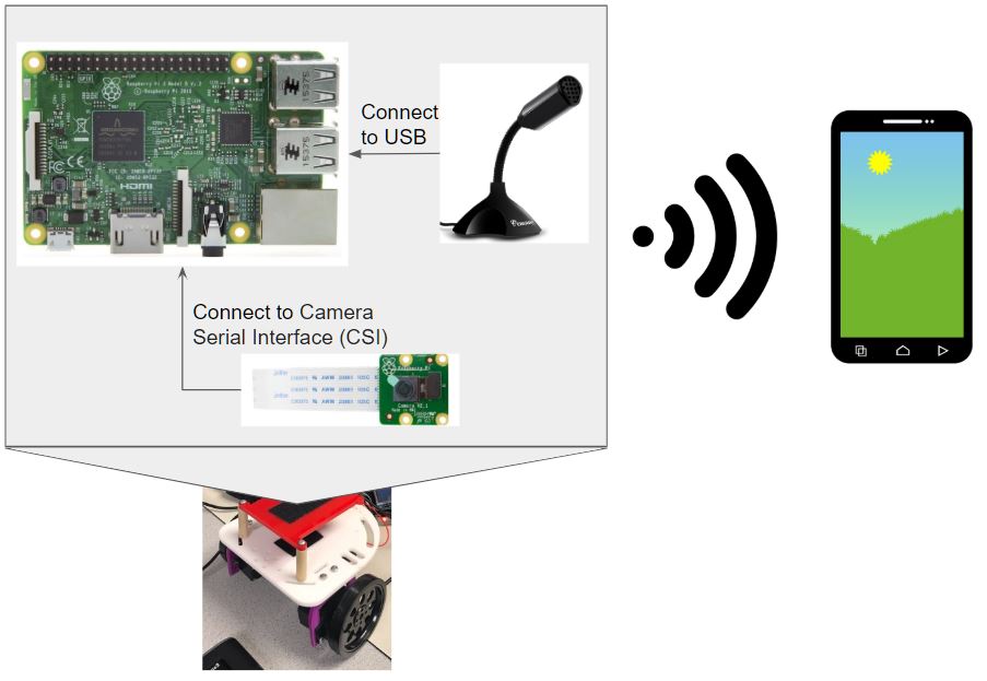
Diagram of the overall system of our project
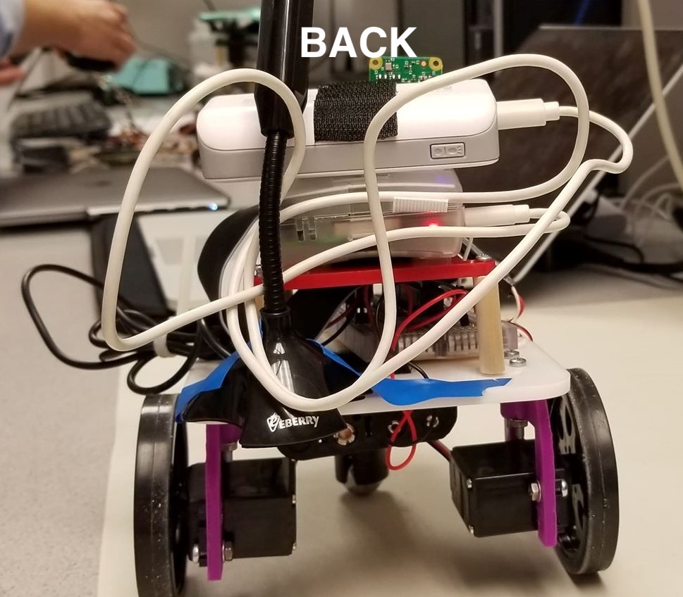
Our project consists of a robot that can move forward, backward, turn left, and turn right depending on inputs from a wireless accelerometer on a phone. The robot can also capture audio through a microphone and video imaging using a camera, both configured onto the robot. The image and audio are transmitted to a phone via WiFi.
By the end of our 5 weeks, we have successfully accomplished the following:
- Implemented socket programming for communication between the robot and phone
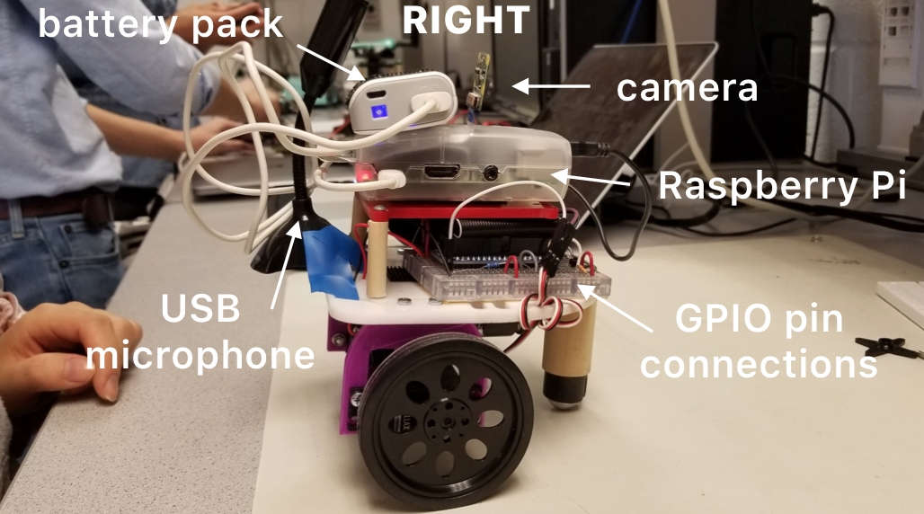
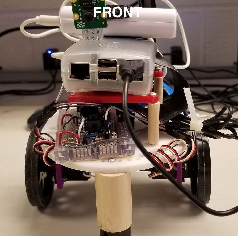
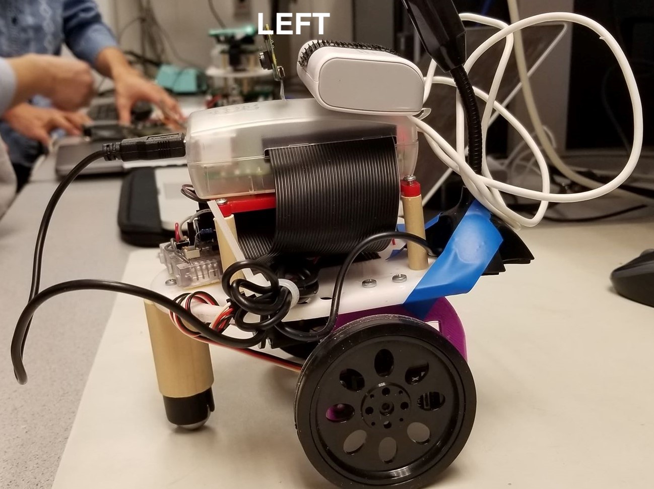
- Built robot using materials provided in Lab 3
- Configured servos for the robot's motion through PWM signals
- Set up Camera and Microphone and livestreamed it online to a website
- Set up phone's accelerometer information to send to pi
- Created an application for the phone to diplay the livestream video and audio
Camera
We used the Raspberry Pi camera and installed it following this
tutorial.
We first connected the camera in the slot in the Raspberry Pi,
which is between the HDMI and Ethernet ports,
with the silver connectors facing the HDMI port.
Then we ran sudo raspi-config in the terminal
to enable the camera. This is achieved by selecting
5 Interfacing Options -> P1 Camera -> Yes.
If the camera option is not available, then an update needs
to be made, which in this case, sudo apt-get update
and sudo apt-get upgrade would need to be run in
the terminal window.
After enabling the camera,
we rebooted (sudo reboot)the Raspberry Pi.
We played around with the camera by taking photos (raspistill -o image.jpg)
and videos (raspivid -o video.h264 -t 10000).
This can be viewed using gpicview image.jpg
for photos and omxplayer -o hdmi /path/to/filename.mp4
for videos.
For livestreaming video, we followed the following
tutorial
and used this code
to stream the live video feed to a website http://<Your_Pi_IP_Address>:8000.
We accessed the video streaming through an Android phone that
is connected to the same WiFi network, enabling the user on the
phone end to view the live feed of the camera without being in
the same area as the camera. We were able to get this to work with
very little latency.
Raspberry Pi camera live feed showing up on phone
Audio
We used this
microphone
which connected to the Raspberry Pi via USB.
To check the USB connections, we entered lsusb in the
terminal. To test out the audio output, we used the
arecord and aplay commands and followed
the following steps from this
tutorial.
We loaded the audio module sudo modprobe snd_bcm2835
and tested the output by recording some sound with
arecord -D plughw:1,0 test.wav and exited the command
when finished recording (control+c). To hear the sound back, we used
aplay test.wav. To adjust the sound of the microphone
we used alsamixer and saved the settings using
sudo alsactl store. We found that the sound was
generally a bit quiet, so turning the microphone volume high
was a good idea.
To make this sound play on the phone, we had to find a way to
make it stream to a website. We found that this would be possible
using DarkIce and
Icecast packages through the
following tutorial.
DarkIce is allows one to record audio and stream it by
encoding the audio and sending the mp3 stream to a streaming server (in our
case, Icecast). Icecast is a audio streaming server, which we utlize
to run the audio stream.
We entered the following three lines in the terminal.
    wget https://github.com/x20mar/darkice-with-mp3-for-raspberry-pi/blob/master/darkice_1.0.1-999~mp3+1_armhf.deb?ra
    w=true mv darkice_1.0.1-999~mp3+1_armhf.deb?raw=true darkice_1.0.1-999~mp3+1_armhf.deb
    sudo apt-get install libmp3lame0 libtwolame0
    sudo dpkg -i darkice_1.0.1-999~mp3+1_armhf.deb
Next, we downloaded Icecast sudo apt-get install icecast2.
On the window that pops up, we selected "Yes" to configure Icecast2.
We used the default hostname "localhost", as well as the default
source password and relay password.
After the installation of Icecast2, we made a config file
sudo nano darkice.cfg for DarkIce.
In the file, we pasted the following configurations:
      [general]
      duration        = 0      # duration in s, 0 forever
      bufferSecs      = 1      # buffer, in seconds
      reconnect       = yes    # reconnect if disconnected

      [input]
      device          = plughw:1,0 # Soundcard device for the audio input
      sampleRate      = 44100   # sample rate 11025, 22050 or 44100
      bitsPerSample   = 16      # bits
      channel         = 2       # 2 = stereo

      [icecast2-0]
      bitrateMode     = cbr       # constant bit rate ('cbr' constant, 'abr' average)
      #quality         = 1.0       # 1.0 is best quality (use only with vbr)
      format          = mp3       # format. Choose 'vorbis' for OGG Vorbis
      bitrate         = 320       # bitrate
      server          = localhost # or IP
      port            = 8000      # port for IceCast2 access
      password        = hackme    # source password for the IceCast2 server
      mountPoint      = rapi.mp3  # mount point on the IceCast2 server .mp3 or .ogg
      name            = Raspberry Pi
We created another file called darkice.sh
and used the command sudo nano darkice.sh
to paste the following configurations.
    #!/bin/bash

    sudo /usr/bin/darkice -c /home/pi/darkice.cfg
To make this file executable, we ran sudo chmod 777 /home/pi/darkice.sh
and ran the following three commands to start the Icecast2 service.
    sudo service icecast2 start

    sudo chmod 777 /home/pi/darkice.sh

    sudo service icecast2 start
We then entered the command select-editor and selected
2 for the nano editor (crontab -e). In the bottom
of the text file that appeared, we pasted the following line,
which alows the Raspberry Pi to wait for 10 seconds before it
starts the stream to initialize:
@reboot sleep 10 && sudo /home/pi/darkice.sh.
After a reboot (sudo reboot) of the Raspberry Pi, we
used the command ifconfig to check the IP address of the
Raspberry Pi (if it has changed), and can now go to the website
http://Your_Pi_IP_Address:8000 to get to the Icecast2 page.
From there, we can click on the M3U button on the top right corner
and it will take us to a livestream feed of the audio.
By going to http://Your_Pi_IP_Address:8000/rapi.mp3,
we could directly play the stream. We added this to the Raspberry
Pi camera code, so that the livestream audio could display on the
website as well.
One problem we encountered in our beginning stages of installing DarkIce
was when we tried to use the wheezy debian
release instead of the buster one. This happened because many
tutorials online for audio streaming were older, and therefore used
and older (first) version of the debian release.
It caused one of our SD cards
to no longer be able to read or write.
Another issue we had with the USB microphone was that the sound
was inconsistent. Sometimes when we would test it, the sound would
be clear, and other times the noise would be so loud that other
outside sounds could not be heard. We found that talking closer
to the microphone generally would produce clearer results. One way
improve the microphone was suggested to us to use an iPhone earbud
microphone, and this can be possibly implemented in the future.
Android Application
Video from the phone's point of view, controlling the robot to make it enter the lab room.
We were able to get the livestream video and audio by using webView on the android phone through this tutorial. We initially tried to use videoView and vitamio but could not get that to work.
As in the tutorial, we initialized a WebView variable and set it up in the onCreate section as such :
      public class MainActivity extends AppCompatActivity implements SensorEventListener {
        private WebView webview ;
        ...
        @Override
        protected void onCreate (Bundle savedInstanceState) {
        ...
        webview =(WebView)findViewById(R.id.webView);

        webview.setWebViewClient(new WebViewClient());
        webview.getSettings().setJavaScriptEnabled(true);
        webview.getSettings().setDomStorageEnabled(true);
        webview.setOverScrollMode(WebView.OVER_SCROLL_NEVER);
        webview.loadUrl(videoURL);

       }
      }
Then, in the activity_main.xml file (under the res/layouts folder), one must also remember to put in a WebView object so that the findViewById" line can find the view and load the website onto that view.
Bugs
If the phone still cannot access the website, one should check their AndroidManifext.xml file (under the manifests folder) if it has the <uses-permission android:name="android.permission.INTERNET"/> line included. We also found a bug where the phone could not access the website if it was not under the same Cornell Wifi as the robot. So, one should make sure that if the Pi is livestreaming the camera and audio information online under the Cornell Wifi that the phone is also using the Cornell Wifi (not data).
Controlling the Robot with a Phone
To control the robot wirelessly, we needed to create a socket to send accelerometer information from the phone (the server) to be received by the Raspberry Pi (the client). All code can be either seen in the Code Appendix section or on the GitHub repository.
1. Configuring the Phone's Accelerometer
We configured the phone's accelerometer using AndroidStudio to create an application.
To configure and use the accelerometer within the phone through the app, we followed some tutorials that showed us how to set up and print out the accelerometer values:
Set up accelerometer
Print out accelerometer values
First, we used an empty template through Android Studio. Then, we followed the tutorial, adding the SensorManager and Sensor variables to the MainActivity class. Next, inside the onCreate function, we configure the SensorManager and Sensor to get information from the phone's accelerometer. Although the tutorial uses the standard default accelerometer, we chose to use the rotation vector accelerometer as it seemed more able to sense turning the phone more easily. An overview of the available sensors on the phone can be seen here.
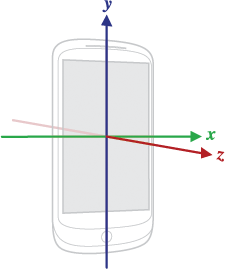
We also then configure the SensorManager to allow us listen to the information from the phone's accelerometer. Next, by using the sensor class, there are two functions that must be included in the MainActivity file : onAccuracyChanged and onSensorChanged. For our purposes, we only use onSensorChanged since we only wanted to read the x, y, and z values output by the accelerometer. In the onSensorChanged function, it takes in a sensor event which then contains the x, y, and z values from the sensor. We then save this information by saving the read values to a string.
public class MainActivity extends AppCompatActivity implements SensorEventListener {

    private static final String TAG = "MainActivity";
    private SensorManager sensorManager;
    private Sensor accelerometer;

    String x,y,z;

    @Override
    protected void onCreate(Bundle savedInstanceState) {
        super.onCreate(savedInstanceState);
        setContentView(R.layout.activity_main);

        sensorManager = (SensorManager) getSystemService(Context.SENSOR_SERVICE);
        accelerometer = sensorManager.getDefaultSensor(Sensor.TYPE_ROTATION_VECTOR);

        sensorManager.registerListener(MainActivity.this,accelerometer, SensorManager.SENSOR_DELAY_NORMAL);
    }


    @Override
    public void onAccuracyChanged(Sensor sensor, int accuracy) {

    }

    @Override
    public void onSensorChanged(SensorEvent event) {
        Log.d(TAG, "X: " + event.values[0] + " |Y: " + event.values[1]);

        x = "xValue: "+event.values[0];
        y = "yValue: "+event.values[1];
        z = "zValue: "+event.values[2];

    }
To see the accelerometer values for yourself, you can use Log.d to print out the values to Android Studio's Logcat. Next, after setting up the accelerometer on the phone, we needed to send it to the RPi.
2. Sending information to the RPi with Socket Programming
Server side ( Android Application )
We used socket programming to send information from the phone to the RPi. The phone was set up as the server by following the information here.
Following this tutorial, after setting up the server as they did, we changed some parts of it to send to the client the accelerometer information continuously. In MainActivity.java, we initialize the server in onCreate. We also include a function that will destroy the server when the application is closed.
        public class MainActivity extends AppCompatActivity implements SensorEventListener {
          Server server ;
          ...

          @Override
          protected void onCreate(Bundle savedInstanceState) {
            ...
            server = newServer(this);
            ...
          }
          ...

          @Override
          protected void onDestroy() {
              super.onDestroy();
              server.onDestroy();
          }
        }
In Server.java, in the run () code section, we see that it has an outputStream that it sends to the Client, in our case the RPi. We change the section to continuously in a while ( true ) loop, print to the outputStream the x, y, and z values recorded in MainActivity. With this, the server has been set up to send across the accelerometer information. We also modified the tutorial code to not print out anything on the application screen.
        @Override
        public void run() {
            OutputStream outputStream ;

            try {
                outputStream = hostThreadSocket.getOutputStream();
                PrintStream printStream = new PrintStream(outputStream);
                while (true) {
                    printStream.println(activity.x + "\n" +
                            activity.y + "\n" +
                            activity.z  + "\n");
                    sleep(1000);
                }
                printStream.close();

            }
            catch (IOException e) {
                e.printStackTrace();
                message += "Something wrong! " + e.toString() + "\n";
            }
            catch (InterruptedException e) {
                e.printStackTrace();
                message += "Something wrong! " + e.toString() + "\n";
            }

            activity.runOnUiThread(new Runnable() {
                @Override
                public void run() {
                    activity.msg.setText(message);
                }
            });
        }
Client side ( from the RPi point of view )
To set up the client code on the Raspberry Pi, we followed the "Echo Client" code in this tutorial.
The HOST value was set to the IP address of the android phone ( which can be found by clicking on the wifi button on your phone ).
We also made sure it was using the same port as was used on the application side in Server.java. A change we made however was to continuously receive data, decode it into ASCII characters, and then send that information to a FIFO. This FIFO is important as it is what we will use to control the robot with the accelerometer. The code can be seen in our repository under client.py.
3. Moving the robot with the accelerometer information
Finally, to move the robot, we read from the FIFO and based on the values from the accelerometer, decide to turn left, right, forward, or backwards. Code for this is found in our repository, under robot_control.py.
To allow the user to stand in any direction and start moving the robot, we first allow for a calibration period in the beginning where it will set the x and z values read to be the setting for which the user wishes to keep the robot still.
Next, after it is calibrated, it continues to read lines from the FIFO. We realized that when the phone (set horizontally) is tilted forward, the z value goes up by 0.1 and x value down by 0.1 from its steady state. To prevent from false forwards however, we set the code up so that it must detect this at least twice before it goes forward. Similarly, to go backwards, it detects that the z value goes down by 0.1 and x value up by 0.1 from its steady state. These threshold values were decided on after trial and error and may need to be adjusted if used on another device.
We also use a buffer here before we actually decide to move the robot backwards. If neither of these conditions are detected, we keep the robot still.
To go left or right, we depend solely on the x values read from the accelerometer. We also prevent the robot from turning if the user is going forward or backwards at that moment. To go right, we see if the x value goes down by 0.1 and to go left, if it goes up by 0.05. Similarly, this values were also found through trial and error and may need to be adjusted if run on another device. We also use a buffer here to detect more than 2 lefts or rights before the robot will actually turn right or left. If neither are detected, it will remain still.
Testing
First, we tested that our robot setup from Lab 3 was still working properly such that the robot could still move. This was important because we actually did find some errors with our servos: our left servo couldn't move. We tried various things such as replacing the batteries and switching out the servo. However, in the end, we realized it was a problem in the code and that we were setting up the wrong GPIO pin.
Then, we tested our camera's configuration on the Raspberry Pi by first taking some sample still pictures. Similarly, we tested the audio's configuration by recording some short snippets using the tutorial.
Next, after confirming that the camera and microphone were properly configured, we tested the livestream of the camera and audio by going on the website. We primarily checked if the latency between the moving on the camera and seeing it on the website was ok. The camera latency was pretty good but the audio latency was slow ( varied from 3 seconds to 20 seconds ).
We tested the phone application by running it on the phone and seeing that we could see the camera and audio output well, similar to how we saw it on the desktop website.
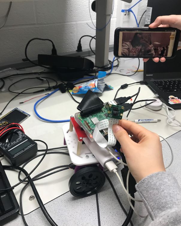
Testing the camera's view on the phone
We tested moving the robot by running the code, and using the application on the phone to move it forward, backward, right, and left. We also tested using the robot at far distances, checking that the Wifi connection would work. However, in testing this, although the robot would still move we saw that the camera latency became very laggy and could not fix this.
Moving the robot with the phone
Robot entering a classroom in Phillips
Result
In the end, we were able to achieve the overall goal of our project: to move the robot wirelessly with our phone. We were able to meet out goals of:
- Learning how to socket program so that the RPi and phone could communicate
- Configure and send accelerometer information from the phone to the RPi
- Move the robot with the accelerometer information
- Set up the RPi camera and audio and livestream it online
- Have the phone be able to see and hear the livestream
Something we weren't able to achieve was using the VR headset in conjunction with our already established design. We decided to not use the VR headset in the end because of timing issues and were not sure if we could callibrate the accelerometer values well with the VR headset. We also decided that just using the phone was also okay and still let us see and hear what the robot sees and hears.
Conclusions
Our project was able to successfully move the robot wirelessly with our phone and finish all project objectives. However, in the end, we discovered that the microphone used did not work well ( latency and sound issues ) and that using an earphone's microphone might've worked better. We also found that although Wifi should be reliable, there still existed some lagging once the robot became too far away. We guess that this may be because the IP address depending on where we are working on the robot ( despite being on the same Cornell Wifi ) changes.
Overall, we believe our project was successful in being able move wirelessly and allow someone to go enter a classroom without beng there themselves.
Future Work
In the future, this project could be improved on by implementing a few more objectives:
- We could implement the VR headset and re-configure the thresholds for turning backward, forward, left, and right when the VR headset is in use. In using the VR headset, one could also try to configure or get a new camera that would allow the user to feel like they are the robot ( as VR view is different from regular flat camera view ).
- We could fix the latency and audio issues of the microphone by using a different microphone. Nowadays, the microphones used on earphones ( like Apple's ) are good enough to filter out other noises and focus only on the speaker. We could've used and try to configure this microphone instead for better quality.
- We could fix the robot architecture and design to be taller and allow for a more smoother and human-like view from the camera. Since the robot is small, the view that it sees is from the ground which doesn't actually let the user see the screen of any room ( unless the screen of the room is on a lower level compared to the robot ). The robot could be redesigned to be taller, and also firmly place the camera so that it does not move so much while the robot is moving.
Work Distribution
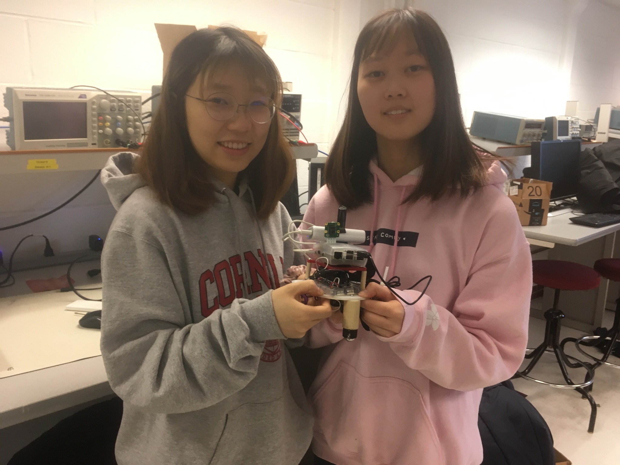
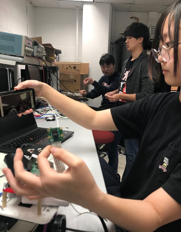
Project group picture
Christine
cya6@cornell.edu
Worked on the building the robot, configuring the android phone application, accelerometer, and socket programming.
Sophie
bh377@cornell.edu
Worked on building the robot, configuring camera and audio streaming, and connecting the parts.
Parts List
- Raspberry Pi Camera V2 $25.00
- Microphone $8
- Phone - Used student's existing android phone
- Raspberry Pi, LEDs, Resistors, Wires, Robot Parts- Provided in lab
Total: $33
References
PiCamera DocumentAccelerometer Tutorial 1
Accelerometer Tutorial 2
Android Sensor Information
Android Socket Programming
Python Socket Programming
WebView on Android Phone